HBM Power Consumption and Thermal Issues Become Core System-Level Design Bottlenecks
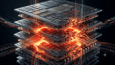
High-Bandwidth Memory (HBM) has become essential for modern AI accelerators and high-performance compute nodes because it delivers massive on-package bandwidth and high energy efficiency per bit transferred. Yet as HBM stack counts, per-die speeds, and module counts per accelerator increase, power consumption and thermal management move rapidly from component-level concerns into system-level bottlenecks.
Why HBM changes the thermal equation
HBM’s advantages—very wide interfaces and stacked dies placed close to compute—also concentrate power in smaller volumes. Compared with off-package DRAM, HBM places far more bandwidth and power density within a single module footprint. Key reasons HBM stresses thermal and power subsystems:
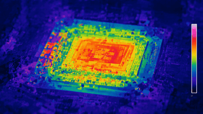
- Higher power density per module: Multiple DRAM dies stacked in a small package create hotspots that are difficult to dissipate with traditional air cooling.
- Increased module counts per accelerator: Modern accelerators often require several HBM stacks directly attached to the die, multiplying package-level heat flux.
- Higher operating voltages and currents for power-delivery: Delivering stable power to stacks and avoiding IR drop becomes challenging at the fine scales HBM demands.
- Stack-internal thermal paths: Heat generated in inner dies must traverse multiple interfaces to reach heat spreaders or interposers, creating thermal gradients and potential reliability stress.
These factors jointly push thermal issues from a local package engineering problem to a system-architecture constraint that affects board layout, chassis design, rack cooling, and datacenter infrastructure choices.
Quantifying power and thermal magnitudes
Providing clear numbers helps planners estimate the scale of the challenge. The following figures are representative ranges based on industry reports and pilot-system measurements through mid-2026; use them as starting points and adjust for specific module generation and stack counts:
- Per-stack power draw: Typical HBM stacks (HBM2E/HBM3 class) in production-era modules draw on the order of 10–40 W per stack under heavy workload; mid- to high-stack-count HBM3e/HBM4 pilot modules can draw 30–120 W per stack depending on frequency, IO toggling, and die count.
- Per-accelerator memory power: An accelerator with 6–12 HBM stacks can therefore have memory-only power budgets ranging from ~100 W to over 1,200 W depending on generation and utilization patterns.
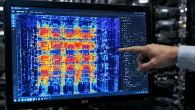
- Heat flux at the package: Localized heat flux densities on HBM module surfaces can exceed 50–150 W/cm² in worst-case hotspots for high-stack-count modules under peak loads, far above typical CPU/GPU maxima in earlier generations.
- Thermal resistance budgets: Achieving junction-to-ambient thermal resistance low enough to maintain die junctions within reliability envelopes often requires package-to-heat-sink thermal resistances on the order of 0.05–0.2 °C/W or better for multi-stack modules integrated into dense accelerators.
These numbers show that HBM memory can represent a dominant portion of an accelerator’s thermal budget and, when multiplied across many servers in a rack, a significant fraction of rack-level heat dissipation.
Failure modes and reliability concerns
HBM thermal stress manifests in multiple technical failure modes and long-term reliability issues if not properly managed:
- Thermal throttling: Elevated junction temperatures force controllers to reduce frequency or pause traffic to avoid permanent damage, reducing sustained performance.
- Bondline delamination and interface degradation: Repeated thermal cycling and high steady-state temperatures can cause underfill or hybrid-bond interface degradation, increasing electrical resistance and risking opens.
- Electromigration and metal diffusion: High current density in power TSVs or RDLs combined with elevated temperatures accelerates electromigration, decreasing lifetime and increasing soft-failure rates.
- Leakage current increases: DRAM cell leakage grows with temperature, raising refresh power and increasing overall thermal load in a feedback loop if not controlled.
- Mechanical stress and warpage: Thermal gradients across stacked dies and interposers can create warpage that breaks fine-pitch hybrid bonds or misaligns interconnects.
Mitigating these failure modes requires both short-term operational controls (power capping, throttling policies) and long-term design investments in thermal paths and materials.
Cooling solutions and trade-offs
Several cooling approaches are in use or under active development. Each has trade-offs in capital cost, operational complexity, integration time, and effectiveness:
Advanced air cooling (optimized heatsinks, directed airflow)
- Advantages: Lower capital cost, compatibility with existing datacenter infrastructure, simpler maintenance.
- Limitations: Insufficient for top-tier HBM stacks and multi-stack GPUs at high utilization; struggles to remove high local heat flux without excessive acoustic and fan-power penalties.
- Use case: Lower-stack-count HBM modules or mixed-use clusters with modest sustained utilization.
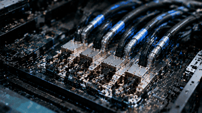
Liquid cooling (cold plates, rear-door heat exchangers)
- Advantages: Far higher heat removal per unit area, lower delta-T’s enabling sustained high-performance operation, and reduced need for aggressive throttling.
- Limitations: Higher integration complexity, leak-risk management, increased rack-level plumbing and facility changes, and higher upfront CAPEX.
- Use case: High-density accelerator pods and training clusters where sustained utilization justifies the infrastructure cost.
Direct-to-chip microfluidics and jet impingement
- Advantages: Highest local cooling efficiency, precise hotspot control, and potential for lower thermal resistance than conventional cold plates.
- Limitations: Significant engineering complexity for reliability, sealing, and maintenance; potential contamination risk and high integration cost.
- Use case: Extreme performance servers where per-node performance dictates the economics (hyperscaler high-performance training fleets, specialized HPC sites).
Two-phase cooling and immersion
- Advantages: Uniform cooling, elimination of hot spots, ease of removing heat at the system level; immersion supports high density with fewer plumbing requirements per server.
- Limitations: Requires significant datacenter redesign, concerns about serviceability and compatibility with certain materials, and operational process changes.
- Use case: Ultra-high-density datacenters or specialized HPC installations where operational practices can be adapted for immersion maintenance.
Choosing among these approaches involves weighing CAPEX, OPEX (including pump and coolant energy), reliability risk, and co-design complexity with module and package vendors.
Power-delivery and board-level considerations
Thermal solutions must be matched by power-delivery designs that avoid IR drop and local hotspots from resistive losses. Key considerations include:
- Local regulation and point-of-load converters: To minimize distribution losses, it is often advantageous to place high-efficiency regulators close to HBM stacks or the accelerator package.
- Wide copper planes and multi-layer PDNs: Low-impedance PDNs reduce resistive heating; designers frequently add dedicated power TSV arrays and thicker RDL metal for current-carrying capacity.
- Decoupling and bulk capacitance: High-frequency switching needs require careful decoupling placement to reduce transient droops that can trigger local overdrive and thermal events.
- Connector and carrier design: Mezzanine carriers and interposers must be engineered to route high currents without excessive localized heating; connector thermal resistance and contact reliability under cycling are important.
- Electrical-thermal co-simulation: Tools that co-simulate PDN behavior and thermal effects help identify hotspots before prototype builds and allow for mitigation via layout changes or cooling placement.
Power and thermal design are tightly coupled: poor PDN design increases thermal load, and inadequate cooling constrains PDN options through derating for thermal margins.
Co-design best practices
To avoid surprises, practitioners recommend integrated co-design between package, board, chassis, and datacenter teams. Practical best practices include:
- Early thermal budgeting: Establish memory and accelerator thermal budgets early in architecture definition and iterate till component-level targets are mutually achievable.
- Prototype thermal maps: Use instrumented prototypes to validate hotspot locations and flux; iterate package-to-cooler interfaces to lower thermal resistance where it matters most.
- Design for throttling and graceful degradation: Implement fine-grained power controls so workloads can be rebalanced to avoid sudden full-system throttles that reduce overall throughput.
- Standardize mechanical interfaces for cooling: Standard carrier footprints and cold-plate mounts reduce custom integration time and speed system qualification.
- Run reliability stress tests replicating datacenter cycles: Validate thermal cycling, humidity, and power-variation scenarios representative of real operations to catch latent failures early.
Operational strategies for hyperscalers and datacenter operators
Beyond design, operators can adopt operational levers to manage HBM thermal constraints across fleets:
- Workload scheduling and thermal-aware placement: Avoid colocating many peak-thermal nodes in a single rack or aisle when possible; schedule sustained high-power workloads across multiple cooling zones.
- Dynamic power capping: Use telemetry-driven throttling to cap memory power in real time and reduce long-term thermal stress while maintaining predictable performance profiles.
- Zone-based cooling upgrades: Incrementally upgrade cooling capacity in hot aisles with targeted liquid manifolds rather than full-datacenter overhauls to reduce CAPEX exposure.
- Predictive maintenance: Monitor thermal and current telemetry to predict module degradation and preemptively service or replace units, reducing unexpected outages and reliability incidents.
Supply-chain and OSAT implications
Packaging houses and material suppliers must adapt to the thermal demands of HBM in several ways:
- Material innovation: Demand for higher-thermal-conductivity TIMs, low-stress underfills, and thermally conductive RDL fillers is growing. Materials that balance thermal conduction with electrical isolation are particularly valuable.
- Package-level thermal testing: OSATs need to expand package-level thermal validation services, including rapid thermal cycling, localized heat-flux testing, and electro-thermal reliability testing during qualification flows.
- Integration of microfluidic or cold-plate-ready package options: Offerings optimized for direct liquid cooling simplify downstream integration for system OEMs and hyperscalers.
- Design kits and co-engineering: Providing mechanical and thermal reference designs accelerates customer qualification and lowers integration risk.
Economic trade-offs and TCO perspectives
Moving to advanced cooling and power-delivery options increases CAPEX and potentially OPEX, but these costs must be evaluated in total-cost-of-ownership (TCO) terms:
- Higher upfront CAPEX for liquid cooling may be offset by higher utilization and faster time-to-train, reducing cost-per-training-run over the cluster life.
- Improved thermal reliability lowers replacement and warranty costs, and reduces unexpected downtime that can be catastrophic for multi-million-dollar training jobs.
- Energy efficiency gains from reduced data movement (enabled by HBM proximity) yield operational savings that accumulate over time, improving ROI for HBM-enabled clusters despite higher hardware costs.
A rigorous TCO model will include CAPEX, cooling infrastructure, power costs, utilization improvements, expected reliability-related replacement rates, and performance-per-dollar metrics specific to the workloads in question.
Emerging technologies and research directions
Several technical advances promise to reduce the thermal pain points of HBM over the medium term:
- Higher thermal-conductivity TIMs and novel fillers: Developments in ceramic and graphene-based fillers that provide high thermal conductivity with electrical insulation will improve package-level heat extraction.
- Integrated heat spreaders and embedded microchannels: Co-design of interposers with embedded microfluidic channels or high-conductivity heat spreaders reduces thermal path length from die junction to coolant.
- Lower-power DRAM process innovations: Process node and cell-architecture improvements that reduce per-bit power lower the absolute thermal load of HBM stacks.
- Active thermal management at die level: Embedded thermal sensors and fine-grained power gating per bank or die allow runtime reduction of hotspots without full-stack throttling.
Adoption of these technologies depends on coordination among memory makers, OSATs, equipment vendors, and system integrators to ensure manufacturability and reliability at scale.
Practical checklist for system architects
To operationalize readiness for HBM thermal constraints, use the following checklist during design and procurement:
- Estimate worst-case memory power per module and multiply by maximum module count per node to get memory-only thermal budget.
- Allocate a conservative margin (20–30%) for unexpected hotspots and early-life higher-power behavior during qualification runs.
- Specify cooling interface and mechanical mounting early to avoid late-stage redesigns; prefer standardized cold-plate footprints when available.
- Run electrical-thermal co-simulations early, iterate PDN and TIM choices to reduce local delta-Ts at hotspot locations.
- Plan for monitoring and telemetry hooks for power and temperature on the carrier and at the node-level to enable predictive thermal management.
- Negotiate service-level and qualification terms with memory and package suppliers that include thermal performance guarantees and joint debugging processes.
What to watch next (leading indicators)
Key signals that will indicate whether thermal bottlenecks are being addressed or will worsen include:
- Announcements of HBM modules with explicit per-module thermal specifications and recommended cooling interfaces.
- OSAT and memory-maker reference designs for cold-plate and microfluidic-ready packages.
- Case studies from hyperscalers showing measured per-node energy efficiency improvements and thermal management approaches in large deployments.
- Material supplier releases of higher-k TIMs and validated underfill materials with improved thermal conductivity and low-stress profiles.
- Standardization efforts for mechanical and thermal interfaces across module vendors that reduce integration friction.
Conclusion
HBM delivers critical bandwidth and latency advantages for AI and HPC workloads, but those advantages come with concentrated power and thermal challenges that now define system-level design constraints. Addressing these bottlenecks requires integrated co-design across package, board, chassis, and datacenter infrastructure; investments in advanced cooling and power-delivery; and close collaboration between memory suppliers, OSATs, OEMs, and hyperscalers. Pragmatic strategies—early thermal budgeting, prototype validation, adoption of liquid or immersion cooling where justified, and designing flexible throttling and scheduling policies—allow organizations to capture HBM’s performance benefits while managing reliability and TCO. As HBM generations evolve, thermal management will remain a core system design discipline rather than an afterthought.